
Electric Bilge Pump Installation
This guide concentrates on wiring a new bilge pump installation in small craft. It explains why a manual bilge pump is a necessary backup, then focuses on practical, safety-first wiring: selecting cable and protection, wiring automatic (float) and integrated pumps, adding a manual override, routing, testing, and common pitfalls.
I will not discuss the sizing of the pump here, as there are too many variables for a general guide. Follow the manufacturer’s guidelines and appropriate rules and regulations for your area. A de facto standard for small-boat bilge pumps is the Rule brand, a subsidiary of Xylem. Their website contains a lot of useful reference material. If you don’t have a local stockist, there is a Rule store on Amazon.
Why is a manual bilge pump also necessary?
Always install a manual bilge pump as a backup. Dead batteries, wiring faults, corrosion, or debris can render electrical pumps inoperable. A simple manual pump provides a reliable, non-electrical means to remove water in an emergency and is an essential part of redundancy.
Key principles before you start your bilge pump installation
- Match wiring and fuse to the pump’s rated current and the length of the run (voltage drop matters, especially on 12V systems). Always check the pump’s specification plate/manual for rated current (amps) at your system voltage.
- Protect the circuit close to the battery with a fuse or circuit breaker sized to protect the wire (and comply with the pump manufacturer’s recommendation). Place this within 300 mm (12 in) of the positive busbar.
- Use marine-grade, tinned copper wire and corrosion-resistant terminals. Seal connections with heat-shrink and/or waterproofing.
- Route wiring up and out of the bilge where possible, secure with ties, and avoid chafing against sharp edges.
- If you want unattended/automatic operation, use a float switch or solid-state sensor rated for the pump current, or drive a relay coil with the float and let the relay handle the pump current.
Bilge Pump Installation: Materials and tools checklist
- Bilge pump (note rated voltage and amp draw)
- Float switch (separate) or integrated automatic pump
- Marine tinned copper wire (sized to pump amps and run)
- Inline fuse holder or DC circuit breaker (see sizing below)
- SPST or 3-position switch (Manual/Auto/Off) for helm control (optional)
- Automotive-style relay (30–40A typical) if using a switch/float to drive the pump indirectly
- Pilot light (optional)
- Piezo buzzer for an audible alarm (optional)
- Ring terminals, butt connectors, and marine crimp sleeves
- Heat-shrink tubing or heat-shrink butt connectors, corrosion inhibitor
- Cable ties, conduit/loom, adhesive mounts
- Screwdrivers, crimper, wire stripper, multimeter
- Sealant for any new through-hull work (if replacing discharge fittings)
Sizing wire and protection (practical rules)
- Determine pump current: Use the pump’s rated amp draw at your system voltage. If you only have GPH/LPH, check the pump datasheet — the manufacturer’s list current draw. If unknown, measure with a clamp meter under running conditions and use the measured running amps for sizing.
- Fuse/breaker sizing: Use the pump’s maximum running current as a baseline. For continuous loads, size the fuse at ~125% of rated continuous current; many pump manufacturers specify a fuse size — follow the manufacturer’s suggestion if provided. The primary purpose is to protect the wire, not to trip during normal operation.
- Wire gauge: Use our wire size calculator to calculate the gauge of wire that you will need. You need the pump’s rated current and the length of the circuit (that is, the total length of wire in the circuit to and from the pump; in other words, the sum of both the positive and negative leg lengths) to enter as inputs to the calculator. Aim for <3% voltage drop. If unsure, oversize the wire rather than undersize it.
Wiring scenarios and diagrams
I’ll use our basic boat wiring diagram as a starting point for these circuits. Check out that article if you need a refresher.
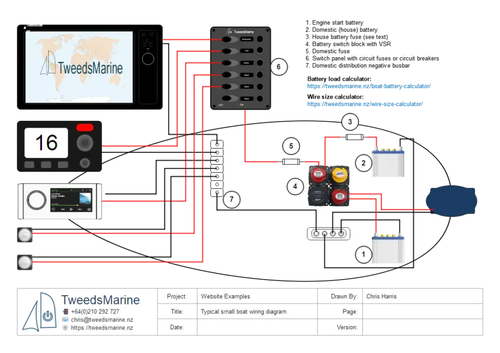
Provide an Always-on power supply
I recommend that bilge pump installations be connected to an always-on distribution. This means that it is powered even when the battery isolator switches are off. This ensures that in an emergency, the pumps will always be available without having to find the battery isolator; remember that the person saving your boat might not always be familiar with it.
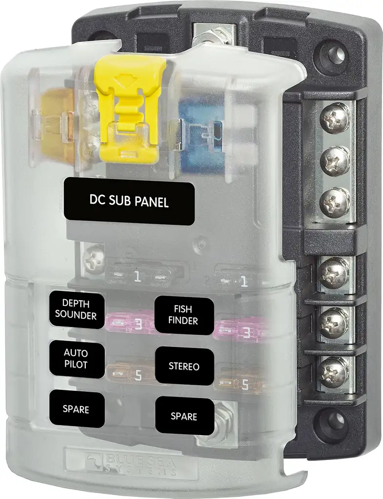
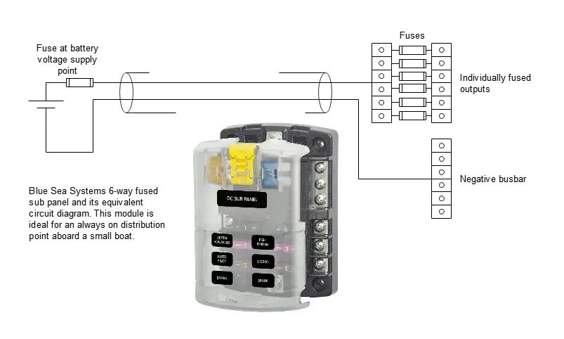
The 6-way fused distribution shown here from Blue Sea Systems makes life easy. Simply, provide a fused positive supply and negative return. Take your always-on loads from the individually fused terminals. Other loads that are typically connected to the always-on distribution are intruder, fire, and bilge alarms, and the VHF radio.
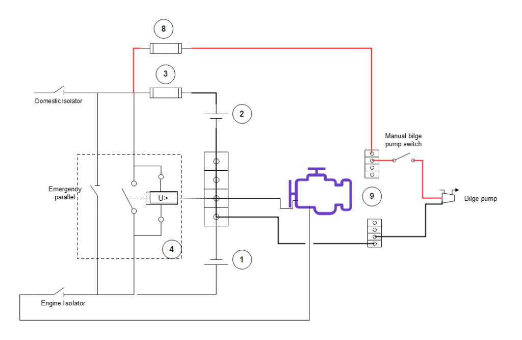
The preceding diagrams provide the foundation that will be used in all of the following pump circuits.
Simple, direct-wired, manual pump
Simple, direct-wired, manual pump with fuse (suitable for pumps with low amp draw and short run).
Additions to the original basic boat wiring diagram to enable the connection of always-on loads.
8 – Fuse for always-on distribution
9 – Always on distribution
Pump Controlled by a Float Switch
Pump controlled by a float switch (float in series) — small pump or float switch rated for pump amps.
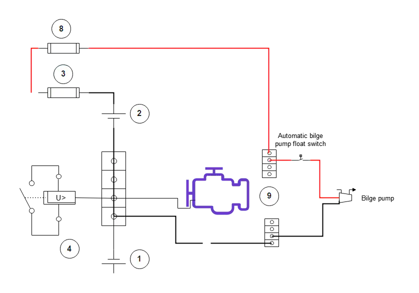
Notes: Use this if the float switch’s contacts are rated for the pump current and the wiring run is short. Many float switches are not rated for high-amp pumps; in such cases, use a relay.
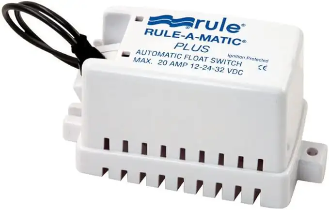
A typical enclosed float switch suitable for pumps up to 20A.
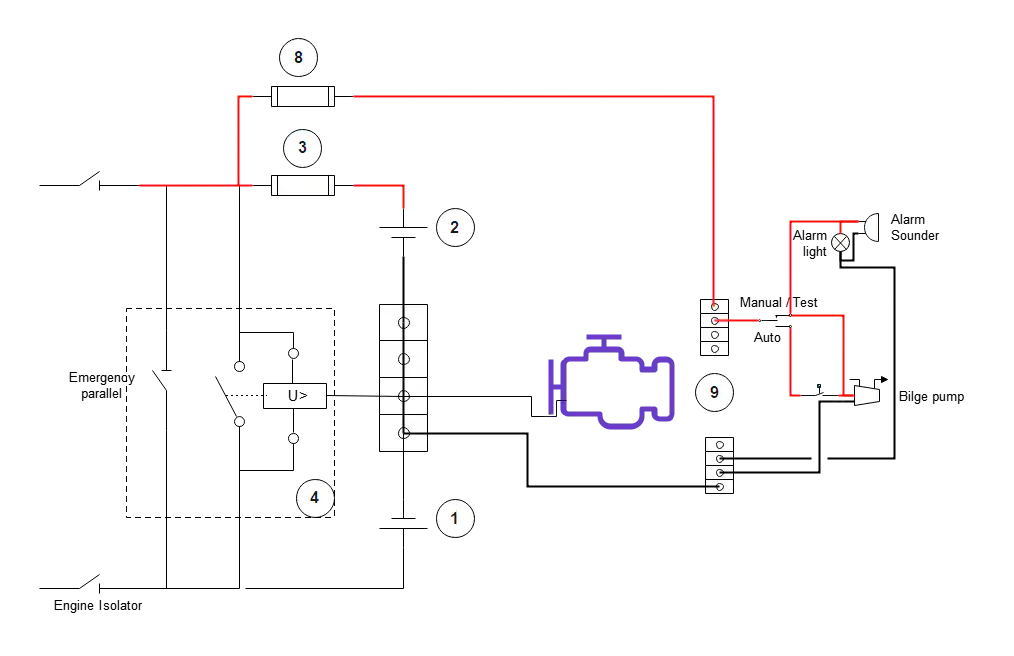
Automatic and Manual Pump
Probably the most common bilge pump installation that you will encounter is the Automatic and Manual bilge pump with an audio and visual indicator alarm.
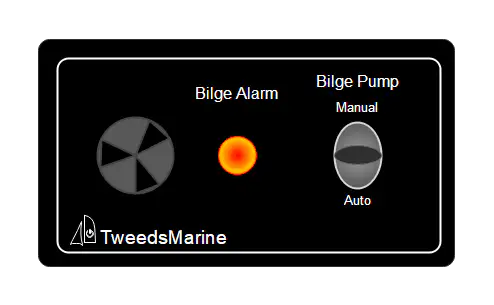
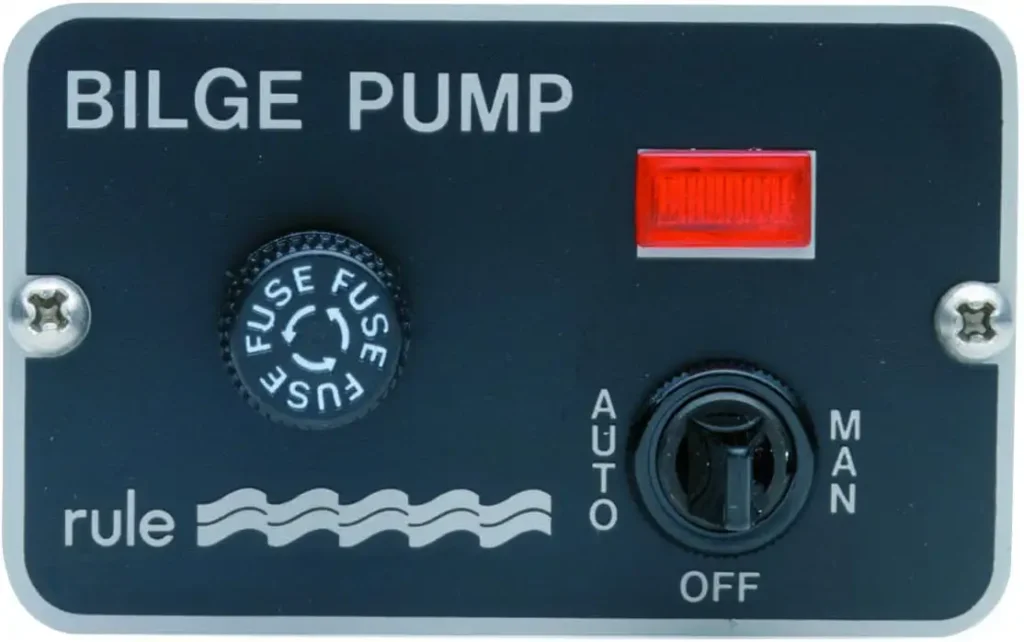
You can buy or make a small bilge pump control panel holding the auto/manual switch, an audible alarm, and an indicator light that can either serve as a visual alarm or as a pilot light to indicate that the bilge pump is in automatic mode.
The control panel can directly control smaller pumps or drive a relay coil for pumps requiring heavy-gauge wire.
These panels made by Rule can be found worldwide.
Pump Operated via a Relay
Float switch driving a relay (recommended for most electric pumps), which has the advantage of small-gauge control wires to the control panel on the dash and a shorter direct run of heavier gauge wire to actually power the pump.
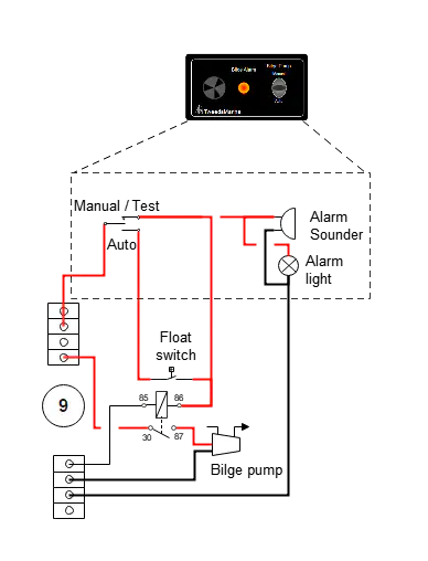
Relay Connections
- Relay 87 – Normally Open (NO) output – Heavy gauge wire to pump positive.
- Relay 30 – (NO) – Heavy gauge wire to battery positive.
- Relay 86 – Coil positive – control wire to Float switch and the manual switch.
- Relay 85 – Coil negative – control wire to battery negative.
- Pump negative – Heavy gauge wire to battery negative.
Note: Fusing is not shown in this diagram.
Manual/test override
Fit a dash-mounted switch that can energise the relay coil directly (manual ON) and bypass float logic for testing or emergency pumping. This is typically a three-way selector switch (Auto/Off/Manual). The manual position is normally a momentary contact with spring return to off, which means that you need to hold it in the on position to operate the pump; this, along with the float switch, ensures that the pump can never run dry or be inadvertently left running.
Integrated automatic pumps
Usually, the simplest blige pump installation: Some pumps have a built-in float switch or electronic water sensor. Note: Some of these pumps are tested by placing your finger against a certain location on the pump’s body; there are no moving test buttons or switches.
They are wired as in the first scenario above for basic pumps or via a manufacturer-supplied control panel to give auto/manual operation.

Multiple pumps and separate circuits
Give each pump its own fused positive conductor and ground. Do not run multiple pumps off a single fuse or inline breaker except as specified by the manufacturer. Each pump should be independently protected and, ideally, independently routed to the battery.
Grounding the Pump
Connect the negative to the vessel’s negative bus or battery negative with the same quality and gauge of wire as the main supply to the pump (the same as the main feed via the relay if one is used). Keep negatives consolidated and labelled. For metal boats, take extra care with dissimilar metal connections and corrosion protection.
Cable Routing for Bilge Pump Installation
- Route all conductors above the bilge waterline and secure to stringers or bulkheads. If the wire must be routed through the bilge, use conduit/loom and protected grommets where it passes through structures.
- Ensure all crimped terminations are fully insulated and strain-relieved; avoid soldered joints in locations that may be stressed mechanically.
- Label both ends of wires (pump and battery/fuse box) with the circuit and fuse rating.
Testing and commissioning Your Bilge Pump Installation
- Continuity and polarity: With the battery disconnected, check continuity and insulation. Confirm all connections are secure and polarity is correct.
- Install the fuse: either at the battery feed or at your always-on panel.
- Bench test: With the pump suspended clear of water, briefly run it (follow manufacturer’s advice) to confirm rotation direction and current draw. Check that the measured current matches the expected.
- In-situ test: Add water to the bilge (or lift the pump into a bucket of water) and verify automatic activation (float) and manual operation. Confirm pump discharges through the through-hull and that there is no leak.
- Voltage under load: Measure battery voltage at the pump while running — it should stay within an acceptable range (12V system generally >11.5V under load; sustained low voltage indicates inadequate wiring, weak battery, or excessive load).
- Verify float behaviour: Confirm float actuates reliably at the intended water level and is not prone to fouling or false triggers in the installed location. Most floats or pumps with integrated floats had a lever or knob that lifts the float for testing.
Note that some float switches need to be oriented fore and aft or athwartships, depending on their design, to avoid false alarms as the boat heels.
Maintenance and Inspection of the Bilge Pump Plumbing
Before every trip, check that the intake to the pump is clear, that all pipes are securely clamped to the pump and to the through-hull discharges.
Maintenance and inspection of the wiring system
- Inspect connections, heat-shrink, and terminals semi-annually (more frequently in harsh environments).
- Check fuse condition and spare fuses on board.
- Re-torque terminal connections after initial run-in period (vibration can loosen crimps).
- Keep float switches free from debris and ensure they move freely. Keep the bilges clean, always!
- Replace any wire showing corrosion, green/white breakout, or brittle insulation.
Common Bilge Pump Installation Wiring Mistakes and How to Avoid Them
- Undersized wire causing voltage drop and reduced pump performance — calculate based on run length and pump amps.
- Fuse is too large or placed far from the battery — the fuse must protect the cable and sit close to the battery positive.
- Relying on float contacts rated below pump amps — use a relay if in doubt.
- Running wiring through the bottom of the bilge without protection — route higher up and secure.
- Sharing discharge hoses for multiple pumps — causes interference/back-pressure (plumbing note; avoid sharing).
Safety notes
- Disconnect the battery before making major wiring changes.
- Use correct polarity; reversing polarity can damage DC pumps and electronics.
- Use only marine-grade, tinned wire and corrosion-resistant connectors in saltwater environments.
- Confirm through-hull discharge is located above the vessel’s static waterline or incorporate an anti-siphon loop as required by your installation situation.
- Always follow the pump manufacturer’s installation and wiring instructions — they supersede generic guidance.
FAQ
Frequently Asked Questions
Why do I need a manual bilge pump if I fit an electric one?
A manual bilge pump installation provides a non‑electrical backup if the battery is dead, wiring corrodes, fuses blow, or the electric pump becomes clogged or fails. It’s essential redundancy — keep one on board and accessible.
How do I choose the correct wire size for my pump?
Use the voltage‑drop calculator and aim for a minimal drop of <3% but some pumps might be designed to run with a 10% voltage drop. When in doubt, select a larger gauge wire; the pump manufacturer’s wiring guidance takes precedence.
Can I wire the float switch directly to the pump?
Only if the float’s contacts are rated for the pump’s full running current and the wiring run is short. For most pumps, it’s safer to have the float drive a relay that switches the pump current.
When should I use a relay?
Use a relay whenever the float switch or helm switch cannot safely carry the pump’s running amps. A relay lets a small control current operate the pump through a high‑current contact, reducing wear and increasing safety.
Should each pump have its own fuse and cable?
Yes. Give each pump its own fused positive conductor and ground. Do not share a fuse between pumps unless the manufacturer explicitly allows it.
Can two pumps share the same discharge hose or through‑hull?
No. Sharing discharge lines can cause backflow, interference, and unintended pump loading. Each pump should have its own discharge path or properly engineered manifold with check valves (used carefully).
Are check valves recommended in bilge discharge lines?
Generally, avoid unnecessary check valves; they can stick or clog. If used, choose high‑quality marine fittings and install them where they can be inspected and serviced. Ensure an anti‑siphon loop is present where required.
How often should I test the pump and float?
Monthly checks are a good minimum: add water to the bilge to test automatic operation and exercise the manual override. Clean strainers and inspect wiring and hoses at the same time.
The pump runs, but no water is discharged — what now?
Likely culprits are a clogged strainer, an airlock in the hose, a kinked hose, or a closed or blocked through‑hull. Check the intake, hose routing, and discharge fitting; clear debris and re‑test.
The pump runs continuously — what does that mean?
Either the float switch is stuck or faulty, wiring has a fault, or there is actual ongoing ingress. Inspect the float and bilge for leaks, then test/replace the float switch if needed.
Should I fit an alarm for high bilge water?
Yes. A visual and/or audible high‑water alarm at the helm gives early warning that the pump is overwhelmed or that there’s a failure. Wire alarms to a reliable power source and test them regularly.


