The Universal Basic Boat Wiring Diagram
I am often asked for a basic boat wiring diagram. While there is no such thing as a universal diagram, I decided to present a minimal diagram as a starting point that may suit typical small power boats (or trailer sailers).
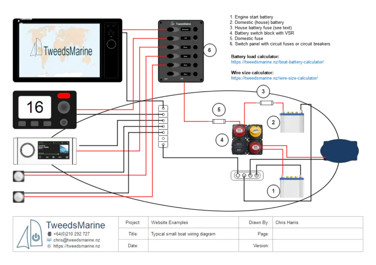
Here is what a basic wiring diagram might look like for a small trailerable powerboat typically used for day trips and fishing.
Remember that this is an overview of the general characteristics of basic boat wiring and that there is no one-size-fits-all solution. If you have doubts about what you are doing, don’t be afraid to ask a pro.
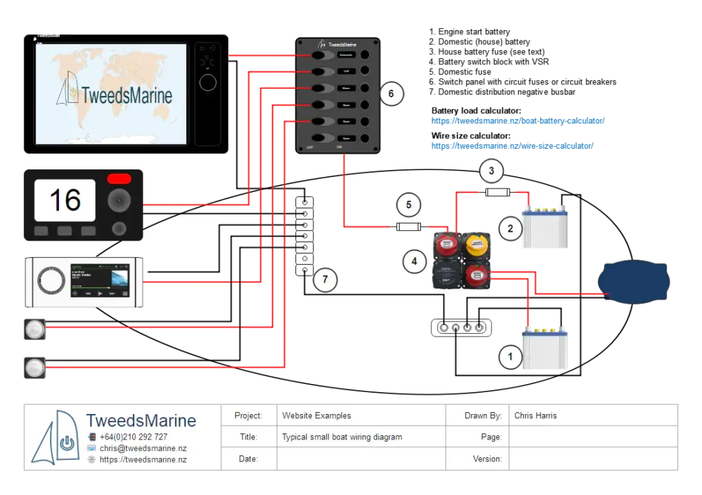
And the same wiring, here presented in schematic format.

Let’s break the wiring on a small boat into its constituent parts and briefly describe their function. Refer to the numbered circles on the diagrams.
All wiring on a boat should be marine grade, which means multi-stranded and tinned copper. Nothing else should be used.
What I Will Not Cover in this Article
I have chosen to leave bilge pumps off these diagrams and will cover bilge pump wiring separately. The bilge pump(s) could be switched via the spare circuit breaker, but as the saying goes, the devil is in the details.
Like bilge pumps, I will not be discussing bonding the negative to the hull (or not bonding it) in this article. Suffice it to say that none of the bonding cables should be part of the circuits described here, and none of these cables should be part of a bonding system.
The Parts of a Basic Boat Wiring Diagram
I’m not going to cover the engine’s start circuit here, as this is dependent on the type of engine and will usually all be handled by the wiring loom and control panel supplied with the engine. You should only need to connect the positive and negative battery feeds to the engine studs.
1 – The Engine Battery Cables and Switch
The type and size of the engine start battery will be specified in the engine installation manual, which should also contain guidelines on the correct wire gauge to use.
Typically, on small boats, the engine start circuit is not fused; provided the cables are double-insulated and short (which they should be), this prevents nuisance blowing of the fuse when the starter motor stalls or a similar issue occurs.
Some standards/regulators or installers recommend very large fusible links or circuit protection mounted very close to the battery to protect wiring in some engine installations — local regs (ABYC / AS/NZS / European RCD) vary.
Any fuse designed to protect cables from a battery should be mounted as close to the battery as possible; regulations vary around the world as to the maximum distance from the battery that the fuse can be located. To be sure that you are protected, you can fit Marine Rated Battery Fuses (MRBF), which bolt directly to the battery terminal.

- A cable connects the engine block to the battery negative busbar (Usually a nickel-plated copper bar with substantial machine screw terminals).
- From the busbar, the cable runs to the negative terminals of both batteries.
- The positive terminal of the battery is connected to one terminal of the engine isolator switch.
- The engine isolator switch is connected to the large terminal on the starter motor solenoid.
Refer to the installation manual that came with the engine for guidelines on the correct cable size to use. If it’s not provided, find the maximum current rating for the starter motor and use the wire size calculator to calculate the correct gauge.
The engine isolator must be sized to easily handle the engine’s worst-case current draw.
All terminals must be crimped very securely onto the cables using lugs that match both the cable gauge and fastening bolt diameter exactly. Borrow, hire, or buy a proper heavy-duty crimping tool; don’t skimp on this part!
Never solder the terminals onto cables connected directly to batteries such as these. In a fault condition, the current can easily heat the cable to the point of melting the solder, allowing it to fall out and potentially cause a short circuit and a fire.
Domestic Battery and Switch Panel
The domestic battery capacity should be matched to the expected loads. Use this boat battery calculator if you haven’t already calculated the capacity for your boat.
Unlike the engine circuit, the domestic circuit is always fused. Depending on where you are in the world and the exact lengths of cable, there may not be a requirement for a fuse (3) in the circuit from the domestic (or house) battery to the battery isolator. Check your local regulations if in doubt.
The cables connecting the domestic battery to its fuse (if fitted), to the isolator, and to the negative busbar must all be sized to carry the engine start current if you plan to use the emergency parallel option. In other words, use the same size cable as the engine cable, assuming similar circuit length.

The circuit from the domestic isolator to the switch panel is usually relatively long on most installations. The wire size for this circuit, isolator > fuse > switch panel and domestic negative busbar > battery negative busbar, will be much smaller than the wires from the battery to the isolator.
This means that this circuit must be fused (5) very close to the isolator switch. To calculate the correct gauge and fuse size, use the wire size calculator. To calculate the maximum current draw for this circuit, look up the maximum current for each device you plan on connecting (or if your switch panel has circuit breakers, add up the rating of all the circuit breakers.
Example: For the circuit panel above, the capacity of all the circuit breakers sums to 65A. If the circuit length is 6m (3m each leg) and we plug those values directly into the calculator, allowing 3% voltage drop, we get a cable size of 50mm2; that’s kinda big and expensive.
As none of the loads are continuous except maybe the instruments and navigation lights, we can use a rule of thumb and calculate 125% of the continuous loads, and sum the non-continuous loads, taking 35%.
In our example:
10A for the instruments, 10A for the radio 20×1.25 = 25A plus 45 x 0.35 = 15A for the remainder results in a calculated load of around 40A. Plug this into the calculator at 3% voltage drop, and we get 25mm2.
Still seems big! What can we do? We only need to respect a 3% voltage drop in a cable under normal operating conditions. So, back to the manuals to find the normal operating current draw for your devices, or better still, measure the current to a similar device with a clamp-type current multimeter.
Let’s say that our research gave us the following values for each circuit:
- Instruments 5A
- VHF radio (transmitting) 3A
- Stereo 3A
- Navigation lights 1A
- Domestic lights 3A
Totals: Continuous draw 8A, intermittent draw 7A
Continuous draw: 8 x 1.25 = 10A
Intermittent draw: 7 x 0.35 ~ 3A
Now we have a much more sensible figure of 13A to work with. Plug this into the calculator, and we get 10mm2. This might seem big to you, and I am sure you have seen boats wired with smaller cables; however, if you want your instrument to give you years of service and your radio to be guaranteed to punch out a good signal in an emergency, this is what you should use.
Remember to include all of the loads that you plan to, or may, add to the switch panel in this calculation.
Battery Isolator Emergency Parallel
Most boats that have a twin battery installation (highly recommended) have an emergency parallel switch (block 4 on the diagrams). This circuit often includes a Voltage Sensitive Relay (VSR). The isolators and VSR can be bought as a modular block from several manufacturers, such as this one from BEP.

The emergency parallel switch enables you to connect the domestic battery to the engine for an emergency start in the case of a flat or failed start battery. The emergency parallel switch should never be left closed for long periods. Close it, start the engine, and turn it off again. Leaving it closed could result in two flat batteries!
The VSR ensures that the engine start battery charges first after a start; once the start battery recovers to a certain voltage, the relay closes and both batteries can charge. This ensures that the start battery is normally isolated from the domestic battery, and domestic loads will not accidentally drain the start battery.
Note: If a VSR is used, the two batteries must be of the same type and chemistry. If they are not the same type, it may be necessary to use a DC/DC battery charger instead. The same applies to some modern engines with “smart” alternators; always consult the manuals or consult a qualified installer.
All of the cabling for these switches should be capable of carrying the full current of the engine starting, except for the VSR cables, which are usually very short. If the isolators and VSR are bought as a modular kit, the cables for the VSR will already be fitted, so you don’t have to calculate anything.
Domestic Distribution Wiring from the Switch Panel
Cable sizing from the switch panel is relatively straightforward. Each circuit must be able to carry current up to the rating of the fuse or circuit breaker. Measure the length of each circuit and plug in the value of the circuit breaker or fuse as the current, using a 10% voltage drop.

For example: A 5A-rated circuit breaker feeds the stereo; the total cable run (there and back) is 4m. Plugging this into the calculator gives us a cable size of 1mm2.
Summary
This article presents a basic boat wiring diagram that gives a practical, easy-to-follow primer for wiring a small trailerable boat. It explains a minimal, sensible layout: a dedicated engine start battery with heavy, short starter cables and a suitably rated isolator or switch; a separate domestic (house) battery feeding a fused switch panel; and a battery-isolator/VSR and emergency-parallel option for starting if required. The focus is on getting the fundamentals right: size starter and parallel cables to carry cranking current, fuse positive conductors as close to the battery as practical, and size the domestic feeder to control voltage drop (aim for ~3% on main feeders, ~10% on branch circuits).
Practical installation tips and safety points are repeated throughout: use tinned marine copper cable, correctly-sized marine lugs and a proper crimp tool, protect terminals with heat-shrink or terminal protectant, and never solder high-current battery terminals. Always total your actual loads, measure run lengths, and use a wire‑size calculator to pick cable sizes. Finally, follow the engine and equipment manuals and local standards, test the emergency-parallel function, and if you’re unsure, get a qualified marine electrician — safety first.
FAQ
Frequently Asked Questions
-
Can I use a smaller cable than the calculator shows?
Not recommended. Smaller cable increases voltage drop and heating risk and will reduce device performance. If cost/space is a concern, calculate precisely for your loads and target voltage drop, and never undersize starter/emergency-parallel cables.
-
Should I always fuse the positive at the battery?
Yes — fuse each positive conductor as close to the battery positive terminal as practical, except where the engine manufacturer explicitly requires an unfused starter cable or a heavy fusible link is recommended. Local regulations vary, so check the standards that apply to you.
-
What about the negative/return conductor — does it need to be the same size?
The DC negative return must be at least the same size as the positive for the same run and load. In marine practice, central negative busbars simplify returns and bonding, but don’t confuse DC negative with hull bonding — they are separate systems and each has its own rules.
-
Can I permanently parallel my start and domestic batteries to share charging?
Permanently paralleling batteries is not recommended. Use a battery isolator, VSR, or DC‑DC charger to manage charging and protect the starter battery. Emergency parallel is fine short-term for starting but not as a permanent arrangement.
-
How do I crimp and protect terminals?
Use a proper marine-grade crimp tool sized to the lug and cable. Use tinned copper lugs, apply heat-shrink or terminal protectant, and torque stud connections to the manufacturer’s spec. Never solder battery terminals that will see high currents.
-
How often should I check wiring?
Monthly visual checks are good practice: look for corrosion, loose lugs, chafing, and correct fuse/breaker operation. Periodically check battery resting voltage and perform a cranking/test of emergency-parallel operation.
-
Who should I call if I’m unsure?
If in doubt, consult a qualified marine electrician or your engine installer. Safety first — improper wiring can cause failures or fires.


2 Comments
[…] use our basic boat wiring diagram as a starting point for these circuits. Check out that article if you need a […]
[…] Basic Boat Wiring Diagram […]