Introduction to VHF Marine Radio Testing
Your VHF marine radio is one of the most important safety items on board. The simple act of adding VHF marine radio testing to your maintenance schedule will ensure that your VHF marine radio is working reliably before every season.
Learning the skills required for VHF marine radio testing will enable you to test it anytime you notice poor range or noisy reception.
This guide walks boaters with no technical background through simple, practical checks you can do yourself with a couple of basic tools. The goal is to help you find common problems (and, where possible, fix them) or gather enough information to give a qualified technician a clear picture.
Tools you’ll need (basic, inexpensive)
- Basic digital multimeter (for DC voltage and continuity) — MESTEK digital clamp meter
- Portable VSWR (SWR) meter or SWR/Power meter that covers marine VHF (156–162 MHz) — Fumei RS-40 VHF 140-150Mhz SWR/Watt meter
- Jumper cable to connect the radio to the VSWR tester – Superbat CB UHF Male PL259 to UHF Female SO239 Jumper
- Small screwdriver set, cable ties, electrical contact cleaner, rags, cable sealant tape (I recommend this product from 3M – 3M Electrical Insulation Putty)
- Optional: Set of ferrite cores for interference suppression – Glarks 32pcs Black Clip-on Ferrite Ring Core Set
- Optional: handheld VHF (to compare)
- Optional: Dummy load (a test antenna) – XRDS-RF 25W PL259 UHF Male Plug RF Dummy Load, 50 Ohm
Safety first
- Turn the radio off or put it in standby before disconnecting coax or wiring.
- Never transmit without an antenna or dummy load connected — that can damage the radio.
- If you’re uncomfortable with any step, stop and consult an expert.
What to Test and How
Power Supply
Check the power supply (the most common problem affecting marine electronics)
Why it matters: VHF marine radios need a stable 12 V (or 24 V on larger vessels) supply. Low voltage or noisy power causes poor transmit power, erratic behaviour, or audio noise.
How to check
- Measure the resting voltage at the radio’s power connector with a multimeter. Good systems show ~12.6 V (battery at rest) or 13.8–14.6 V when the engine or charger is running. For a 24 V system, double those values.
- Measure under load: Have someone key the mic (transmit) while you watch the voltage. The voltage should not drop more than 3% of the battery supply voltage (~0.4V) during transmission; a voltage drop greater than 3% suggests a wiring or installation problem.
- Check wiring and terminals: look for corrosion, loose terminals, and green/white oxidation on connectors. Clean and tighten, replace damaged or brittle. Use contact cleaner if necessary.
If problems appear
- Replace corroded terminals, use proper marine-grade cables and crimped connectors.
- If the voltage drops significantly while transmitting, the supply wiring may be too thin or the battery weak. Compare the battery voltage to the voltage measured at the radio to determine whether it is a battery or cable problem. If you suspect the cable is too thin, look up the correct size using the wire size calculator.
This article, part of my series on networking marine electronics, describes some of the typical problems with power supplies and gives guidance on establishing a reliable power supply aboard. Power Management and network reliability
Check the Antenna
Check antenna, coax and connectors (VSWR and physical condition).
Why it matters: The antenna and coax are the path for all radio energy; a bad antenna, loose connector, or damaged coax results in poor range, intermittent performance, and can damage the transmitter.
VSWR stands for Voltage Standing Wave Ratio, but don’t let the name scare you off. For our purposes, it’s simply a way to check how healthy your antenna system is.
When you transmit over your VHF radio, most of the signal should head out through the antenna and into the airwaves. But if something’s wrong—like a damaged cable, corroded connector, or poorly tuned antenna—some of that energy gets bounced back toward the radio. VSWR tells you how much is getting through and how much is coming back.
- A perfect antenna would have a VSWR of 1:1, meaning 100% of your signal is getting out.
- If 10% of the energy is reflected, the VSWR is around 2:1.
- If 25% is reflected, it jumps to 3:1, and so on.
High VSWR isn’t just bad for performance—it can also stress your radio’s transmitter over time. So while engineers might use VSWR for fine-tuning and design work, we’re keeping it simple: it’s a quick “good or bad” check to help you spot trouble before it becomes a real issue.
Curious minds can dive deeper on Wikipedia’s VSWR page—but for most boat owners, a basic reading is all you need to keep your radio working reliably.
How to do a Basic VSWR Check

- Set the radio to low power (1Watt).
- Connect your VSWR meter between the radio and the antenna per the meter instructions.
Insert Diagram here. - Key the mic briefly on an unused channel (or low-power test function) and read the SWR. Good installations typically read below 1.5:1. Values up to 2.0:1 are often acceptable but not ideal. Above 2.5:1 needs immediate attention.
- If you get a very high reading or infinite SWR, check connectors and coax first — you may have an open or short.
- Re-check the VSWR over a wide range of channels to ensure that your antenna is correctly tuned across the entire band.
Optional – If you have a dummy load, you can attach it to the antenna connector of your VSWR meter. This will give the radio an almost perfect antenna to transmit into, and you should therefore see almost perfect results, along with an accurate transmit power reading (see the next section). This has an added advantage that your testing will not be transmitted, and you won’t annoy the neighbours.

Physical inspection
- Look along the coax for chafing, kinks, crushed sections, or water intrusion. Outer jacket damage usually means internal corrosion or moisture.
- Inspect connectors for corrosion or loose fittings. Replace weathered PL-259 / SO-239 or N-type connectors with new marine-grade connectors, and seal with self-amalgamating tape, PVC tape, or adhesive-lined heat-shrink.
- Check antenna mounting: a corroded mount, a loose mount, or a broken antenna base will change the antenna’s grounding and tuning.
If VSWR is high after checking the connectors
- Temporarily swap the antenna with a known-good antenna or dummy load to see if VSWR improves — this isolates whether the antenna or the radio/coax is at fault.
- Use a dummy load (if you have one) at the feedpoint to verify the radio and coax. If SWR is good to the dummy load but bad to the antenna, the problem is the antenna or mount.
Test the Radio’s Power Output
After you have tested the VSWR and rectified any faults, you should check that the radio is transmitting at the correct power levels. Typically a fixed installation will transmit around 25 Watts on high power and on low power, should not transmit more than 1W. Check the manufacturer’s data sheet for the high-power specification of your set. Handhelds will transmit 3 – 6 W on high and should also be under 1W on low power.
Tranmitting into a antenna with acceptable VSWR will give you a reasonable power measurment but for an exact figure you have to test by transmitting into a dummy load.
Check for Interference
Isolating interference from onboard electronics
Why it matters: Modern boats have lots of electronics (inverters, AIS, GPS, chartplotters, bilge pumps, chargers, LED lighting). Some generate broadband noise, causing hiss, static, or blocking weak signals. Cheap LED lights are the prime suspects!
Initial Test
Turn down the squelch control until you hear the background noise and listen to it for a moment. The noise should be “white” noise, which means that you should not be able to hear a pattern or tones.
Switch on all electric and electronic devices on the boat and set them to their normal operating state.
After listening, adjust the squelch up until the noise just stops; this should be the normal operating position for the squelch control and ensures that the radio is operating at its most sensitive receive point (in other words, you will be able to hear weaker signals).
Step through the channels one by one, pausing for a moment on each. If you hear background noise on any channel that should not be there, you should investigate the cause.
Process to isolate
- Turn off non-essential electronics one at a time while listening to the radio to see when the noise stops. Common culprits: inverters/chargers, radar, VHF antenna splitters, faulty alternators and loose/worn brushes.
- If noise is worse when an engine is running, the alternator or its regulator might be the source — fit suppression (ferrite cores, grounding improvements) or have the alternator serviced. Modern alternators will have a suppression capacitor installed by default, but older ones and their after-market replacements probably will not.
- If there is no fault with the noisy device, fit ferrite cores on its cables (power leads, data cables) as close as possible to the noisy device. Ferrites are cheap and effective.
Here is a basic guide on fitting ferrite – How to Use Ferrite Beads: 9 Steps (with Pictures) – wikiHow - Keep audio and data cables separate from power or high-current cables to avoid induced interference.
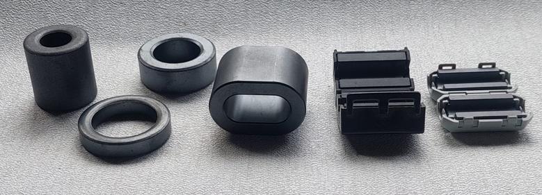
The image below shows a selection of ferrite cores; the easiest to use are the clamp-on type at the right. The others must be threaded onto the cables. In either case getting as many turns through the centre of the core as possible is key. Do not use these on coax cables (antenna cables).
When you can’t find the source
If you are in a marina or other industrial area, consider that the noise may not be coming from your boat. Check this by going for a walk with a handheld radio and monitoring a noisy channel.
Microphone, Speaker and Audio Settings
Check the microphone, speaker and audio settings
Why it matters: Sometimes the radio seems to be “weak”, but it’s just a bad microphone, corroded speaker, corroded microphone connector, or incorrect audio settings.
Checks to do
- Swap the microphone with a spare or borrow a handheld to compare the transmit audio on another radio. If the other microphone sounds fine, replace the mic/cable.
- Check the speaker: play audio and listen for distortion or crackling. Corroded connections or water-damaged speakers should be replaced.
- Clean the microphone connector and mic contacts with contact cleaner.
- Check menu settings: volume, squelch level (too high can mute weak stations), and mic gain if the radio has it.
Channel Settings
Verify channel settings and region (USA vs International)
Why it matters: Radios have channel plans and frequency offsets that differ by region. If set to the wrong plan (USA vs International), you may not hear another station or be transmitting on an incorrect frequency.
What to check
- Consult your radio manual to find where the channel plan/region is set. Commonly, this is a menu option under “Region,” “CH Plan,” or “TX Limits.”
- Ensure your radio is set to the correct region for where you operate. If you travel between regions, check the settings before you go.
What to Expect after Testing and Troubleshooting
Good power: ~12.6 V (rest), and it should not sag more than about 0.4V below the battery voltage under transmit and never below 11.5V.
Good VSWR: ideally <1.5:1; acceptable up to 2:1. Anything consistently above 2:1 needs repair.
Clean reception: minimal hiss when no signals are present; noise that coincides with a device being on indicates interference.
When to call a pro
- You find a high VSWR but can’t isolate whether it’s the antenna or the coax.
- Voltage drops severely under transmit despite good-looking wiring.
- You’re uncertain about safely repairing or replacing coax or antenna hardware.
- DSC alarms or legal requirements are involved — DSC installations are safety-critical.
Perform a Radio Check Call
When you are satisfied that your radio is functioning correctly, do a radio check. Call a shore station such as harbour control or the coastguard. In most countries, they will be happy to give you a signal report. Choose a station that you know you should be able to reach, but that is not so close that reception is guaranteed. You want this to be a true test!
Wrapping Up and Buying Tips
To sum up, the basics of VHF marine radio testing and radio maintenance, testing and fault finding are not difficult. You don’t need an engineer to perform basic tests (although that is sometimes necessary to isolate trickier problems). Most of the tools should be aboard anyway; the only item that I don’t expect many to have aboard is the VSWR meter. You don’t need to spend much on a functional VSWR meter for this type of go / no-go tests. I have identified a few products on Amazon to give you an idea. If you click through on these links and make a purchase, it doesn’t cost you anything, and I may get a small commission to help with the upkeep of this site.
- A basic digital multimeter is indispensable — look for one with DC volts, continuity, and ideally a DC clamp ammeter function (the meter will have jaws that open like pliers, you clamp the meter around a wire and can measure the current flow through that wire). – MESTEK digital clamp meter
- A handheld VSWR meter that covers 156–162 MHz will let you do the essential antenna checks yourself. – Fumei RS-40 VHF 140-150Mhz SWR/Watt meter
- Jumper cable to connect the radio to the SWR meter – Superbat CB UHF Male PL259 to UHF Female SO239 Jumper
- Ferrite chokes – Glarks 32pcs Black Clip-on Ferrite Ring Core Set
- replacement connectors – PL259 with reducers, 6-pack
- marine-grade coax sealant – 3M Electrical Insulation Putty Tape
- Optional: Dummy load (a test antenna) – XRDS-RF 25W PL259 UHF Male Plug RF Dummy Load, 50 Ohm
FAQ
Frequently Asked Questions
How often should I test my VHF marine radio?
At least once a season and before any major trip. Do a quick power and audio check before leaving the dock and a fuller VSWR + interference check annually or whenever you notice reduced range or noisy reception.
My radio seems weak—where should I start?
Check the power first. Measure voltage at the radio (resting ~12.6 V, charging 13.8–14.6 V). Then check for a big voltage sag while keying the mic. If power looks good, check antenna/coax (VSWR and physical condition) and microphone/speaker connections.
What VSWR numbers are okay?
Aim for <1.5:1 (ideal). Up to 2.0:1 is often acceptable. Above ~2.5:1 needs attention — you risk poor range and possible transmitter stress.
My SWR is very high or infinite—what now?
Check connectors and coax first (loose, corroded, or waterlogged cables). Replace or reseal bad connectors. If connectors/coax look good, swap to a known‑good antenna or use a dummy load to isolate antenna vs radio/coax.
How do ferrite cores help, and where do I fit them?
Ferrite clamp‑on cores reduce broadband EMI on power and data cables. Fit them as close as possible to the noisy device and get as many cable turns through the core as possible. Don’t fit ferrites on coax (antenna) cables.
My noise only appears when the engine runs. What’s likely wrong?
The alternator or its regulator could be the culprit. Loose brushes, wear, or missing suppression parts are common causes. Fit suppression (ferrites, grounding improvements) or have the alternator checked.
How do I know whether it’s my antenna, coax, or the radio causing problems?
Use a stepwise swap: 1) Inspect/replace connectors and coax visually. 2) Attach a dummy load—if SWR and power are good, the problem is the antenna or mount. 3) Temporarily connect a known‑good antenna/handheld—if that fixes it, antenna/mount is likely the issue.